SYMAP® Compact - Protection and Control
(F0, F1, F2, F3 and F4)
Code Identifier.
Code No.
SHORT DESCRIPTION
F0
F1
F2
F3
F4
1
F0
Application:
"Protection and control system" Standard equipment
Dimensions:
Housing dimensions (WxHxD): (210x250x87)mm
Dimensions front plate (WxHxD): (210x250x4)mm
Cutout (WxH): (192x232)mm
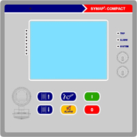
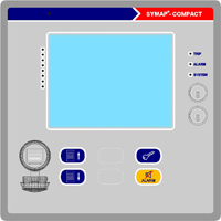
Front plate:
"Stucke"-Logo (Design) LED indication: 3 status-LEDs (Trip: red/Alarm: red-flashing/System: red/green)
8 LED indications (parametrizable, red/green) Membrane keyboard:
4 x memebrane keys (menu navigation/parameter setting/Reset/password) Display:
Graphical LC-Display/Touchscreen (320x240 pixel) Current measurement:
none Voltage measurement: 1 x PT1 (3-phasig: 50 – 130 V / 200 – 690 V); 1 x PT2 (3-phasig: 50 – 130 V / 200 – 690 V); 1 x PT3 (3-phasig: 50 – 130 V / 200 – 690 V);
1 x PT-GND1 (1-phasig: 50 – 130 V / 200 – 690 V) Binary I/O:
Binary inputs: 5 pcs. (10 - 230V AC/DC; rooted)
Binary outputs: 5 pcs. (potential-free contacts) Communication interfaces:
1 x mini-USB, on the side of the housing (parameter setting)
1 x CANBUS 0 (Extended boards)
1 x RS422/RS485 (Modubus RTU; half- and full-duplex)
1 x USB interface (front plate; parameter setting) Control and interlocking: without Gen-Set control functions:
none Protective functions:
ANSI: 25, 25A, 27, 27T, 47, 59, 59G, 60FL, 74TC, 78, 81, 81R, 86
S
-
-
-
-
1
F1
Application:
"Protection and control system" Standard equipment
Dimensions:
Housing dimensions (WxHxD): (210x250x87)mm
Dimensions front plate (WxHxD): (210x250x4)mm
Cutout (WxH): (192x232)mm
Front plate:
"Stucke"-Logo (Design) LED indication: 3 status-LEDs (Trip: red/Alarm: red-flashing/System: red/green)
8 LED indications (parametrizable, red/green) Membrane keyboard:
4 x memebrane keys (menu navigation/parameter setting/Reset/password) Display:
Graphical LC-Display/Touchscreen (320x240 pixel) Current measurement:
1 x CT1 (3-phase:0-25 x In); 1 x CT-GND1 (1-phase:measuring range optional) Voltage measurement: none Binary I/O:
Binary inputs: 5 pcs. (10 - 230V AC/DC; rooted)
Binary outputs: 5 pcs. (potential-free contacts) Communication interfaces:
1 x mini-USB, on the side of the housing (parameter setting)
1 x CANBUS1/CANBUS2 (external communication)
1 x CANBUS 0 (Extended boards)
1 x RS422/RS485 (Modubus RTU; half- and full-duplex)
1 x USB interface (front plate; parameter setting) Control and interlocking: none Gen-Set control functions:
none Protective functions:
ANSI: 46, 49, 50, 50BF, 51, 51LR, 60L, 66, 74TC, 79, 86, 95i, SOTF, CLP
-
S
-
-
-
1
F2
Application:
"Protection and control system" Standard equipment
Dimensions:
Housing dimensions (WxHxD): (210x250x87)mm
Dimensions front plate (WxHxD): (210x250x4)mm
Cutout (WxH): (192x232)mm
Front plate:
"Stucke"-Logo (Design) LED indication: 3 status-LEDs (Trip: red/Alarm: red-flashing/System: red/green)
8 LED indications (parametrizable, red/green) Membrane keyboard: 4 x memebrane keys (menu navigation/parameter setting/Reset/password)) Display:
Graphical LC-Display/Touchscreen (320x240 pixel) Current measurement:
1 x CT1 (3-phase:0-25 x In); 1 x CT-GND1 (1-phase:measuring range optional) Voltage measurement: 1 x PT-GND1 (1-phasig: 50 – 130 V / 200 – 690 V) Binary I/O:
Binary inputs: 5 pcs. (10 - 230V AC/DC; rooted)
Binary outputs: 5pcs. (potential-free contacts) Communication interfaces:
1 x mini-USB, on the side of the housing (parameter setting)
1 x CANBUS1/CANBUS2 (external communication)
1 x CANBUS 0 (Extended boards)
1 x RS422/RS485 (Modubus RTU; half- and full-duplex)
1 x USB interface (front plate; parameter setting) Control and interlocking: none Gen-Set control functions:
none Protective functions:
ANSI: 46, 49, 50, 50G, 50BF, 51, 51G, 51LR, 59G, 60L, 60FL, 64REF, 66, 67G, 74TC, 79, 86, 95i, SOTF, CLP
-
-
S
-
1
F3
Application:
"Protection and control system" Standard equipment
Dimensions:
Housing dimensions (WxHxD): (210x250x87)mm
Dimensions front plate (WxHxD): (210x250x4)mm
Cutout (WxH): (192x232)mm
Front plate:
"Stucke"-Logo (Design) LED indication: 3 status-LEDs (Trip: red/Alarm: red-flashing/System: red/green)
8 LED indications (parametrizable, red/green) Membrane keyboard: 4 x memebrane keys (menu navigation/parameter setting/Reset/password) Display:
Graphical LC-Display/Touchscreen (320x240 pixel) Current measurement:
1 x CT1 (3-phase:0-25 x In); 1 x CT-GND1 (1-phase:measuring range optional) Voltage measurement: 1 x PT1 (3-phasig: 50 – 130 V / 200 – 690 V);
1 x CT-GND1 (1-phase:measuring range optional) Binary I/O:
Binary inputs: 5 pcs. (10 - 230V AC/DC; rooted)
Binary outputs: 5 pcs. (potential-free contacts) Communication interfaces:
1 x mini-USB, on the side of the housing (parameter setting)
1 x CANBUS1/CANBUS2 (external communication)
1 x CANBUS 0 (Extended boards)
1 x RS422/RS485 (Modubus RTU; half- and full-duplex)
1 x USB interface (front plate; parameter setting) Control and interlocking: Control function: 5 switching devices;
Field interlocking: 8 switching devices Gen-Set control functions:
none Protective functions:
ANSI: 24, 27, 27Q, 27T, 32, 37, 40, 46, 47, 49, 50, 50G, 50BF, 51, 51G, 51LR, 51/46VR, 59G, 60L, 60FL, 64REF, 66, 67, 67G, 74TC, 78, 79, 81, 81R, 86, 95i, SOTF, CLP
-
-
-
S
-
1
F4
Application:
"Protection and control system" Standard equipment
Dimensions:
Housing dimensions (WxHxD): (210x250x87)mm
Dimensions front plate (WxHxD): (210x250x4)mm
Cutout (WxH): (192x232)mm
Front plate:
"Stucke"-Logo (Design) LED indication: 3 status-LEDs (Trip: red/Alarm: red-flashing/System: red/green)
8 LED indications (parametrizable, red/green) Membrane keyboard: 4 x memebrane keys (menu navigation/parameter setting/Reset/password) Display:
Graphical LC-Display/Touchscreen (320x240 pixel) Current measurement:
1 x CT1 (3-phase:0-25 x In); 1 x CT-GND1 (1-phase:measuring range optional) Voltage measurement:
1 x PT1 (3-phasig: 50 – 130 V / 200 – 690 V); 1 x PT2 (3-phasig: 50 – 130 V / 200 – 690 V);
1 x PT-GND1 (1-phasig: 50 – 130 V / 200 – 690 V) Binary I/O:
Binary inputs: 5 pcs. (10 - 230V AC/DC; rooted)
Binary outputs: 5pcs. (potential-free contacts) Communication interfaces:
1 x mini-USB, on the side of the housing (parameter setting)
1 x CANBUS1/CANBUS2 (external communication)
1 x CANBUS 0 (Extended boards)
1 x RS422/RS485 (Modubus RTU; half- and full-duplex)
1 x USB interface (front plate; parameter setting) Control and interlocking: none Gen-Set control functions:
none Protective functions:
ANSI: 24, 25, 25A, 27, 27Q, 27T, 32, 37, 40, 46, 47, 49, 50, 50G, 50BF, 51, 51G, 51LR, 51/46VR, 59G, 60L, 60FL, 64REF, 66, 67, 67G, 74TC, 78, 79, 81, 81R, 86, 95i, SOTF, CLP