SYMAP® Compact
• Full Colour Touch Screen Display
• Customisable Menu Screens
• All protection functions included without additional costs
• 4 x Parameter Sets
• 3(4) x Processors for ultimate reliability
• 3 x Status LEDs
• 8 programmable LEDs
• Key Switch Functions (optional)
• Self Diagnostic
• Control and Interlocking of switching devices
• Control of up to 2 Switching Elements
• IEC61850, IEC 60870-5-103, Profibus DP, etc.,
• Stainless Steel Housing
• Pluggable Terminal blocks
• Automatic short-circuiter for CT Connections
• USB Connections as standard
• New Parameter Tool Software
• Multilingual Menu
|
|
|
|
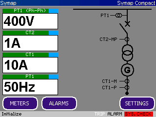
The SYMAP®-Compact device type family offers flexible digital protection and control systems for a wide range of LV and HV applications. At the heart of the SYMAP®-Compact type is a large, full colour, touch screen display. Touch screen display enables quickly and complete programming of all protection and control functions. Alternatively, it can be done via PC using the standard USB connection. The fully programmable nature of these relays gives you an extremely versatile and cost effective solution for all switchgear applications of networks with various protection types concepts
.
SWICHGEAR Control and Interlocking
• single busbar
• double busbar
• duplex systems;
• interlocking at feeder level;
• interlocking at station level
|
|
 |
NETWORKS
• isolated networks,
• resonant-earthed networks and
• solidly, and partially earthed networks
|
|
PROTECTION APPLICATIONS
• Feeder protection
• Transformer protection
• Generator protection
• Motor protection
• Generator Protection
• Generator Protection with machine/engine protection and control and power management system
PROTECTION FUNCTIONS
| 21FL |
Fault locator |
|
|
| 24 |
Overexcitation U/F |
|
|
| 25 |
Synchronizing(Automatic synchronizing/Synchro-check) |
|
| 27 |
Under voltage |
|
| 27/Q |
Reactive power/Under Voltage (BDEW) |
|
| 27/T |
Under Voltage, time-dependent (BDEW; Fault ride through) |
|
| 32 |
Directional Power |
|
| 32N/G |
Zero Power |
|
| 37 |
Undercurrent * |
|
| 40 |
Loss of Field |
|
| 46 |
Negative phase sequence I2> |
|
| 47 |
Phase sequence / Phase balance * |
|
| 49 |
Thermal Replica |
|
| 50 BF |
Breaker failure |
|
| 50 |
Instantaneous Overcurrent |
|
| 50 G |
Instantaneous Earth Overcurrent |
|
| 51LR |
Locked Rotor |
|
| 51 |
Time Overcurrent |
|
| 51 G |
Time Earth Overcurrent |
|
| 51/46VR |
Overcurrent (voltage restrained) |
|
| 55 |
Power factor |
|
| 59 |
Over voltage |
|
| 59N/G |
Neutral Voltage Displacement (NVD) |
|
| 59 N |
Residual overvoltage |
|
| 64REF |
Restricted Earth Fault |
|
| 66 |
No. of Starts (Motor)* |
|
| 67 |
Directional Time Overcurrent |
|
| 67G |
Directional Earth Overcurrent |
|
| 74TC |
Trip circuit monitoring |
|
| 78 |
Vector surge |
|
| 78s |
Power Swing / Out-Of-Step* |
|
| 79 |
Automatic Reclose (AR) |
|
| 81 |
Under / Over Frequency |
|
| 81R |
RoCoF(df/dt) |
|
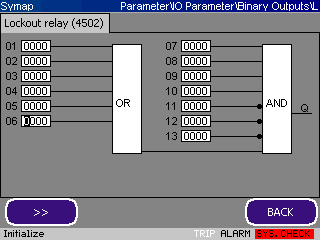
| 86 |
Lockout relay |
|
| 87 |
Current differential protection |
|
| 95 i |
Harmonics stabilizer |
|
| CLD |
Cold Load Detection
|
|
| CTS |
Current transformer supervisiont
|
|
| PTS |
Potential transformer supervision
|
|
| SOTF |
Switch On To Fault
|
|
| TIG |
Transient/Intermittent Ground Fault |
|
| YG |
Neutral Admittance Ground Fault |
|
MONITORING AND MEASUREMENT FUNCTIONS
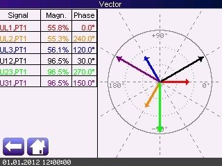
• Up to 9 × phase-to-phase and line voltages of feeder, BUS1 and BUS2
• Up to 6 × phase feeder current (average/max. value)
• Frequencies of all systems (min./max. value)
• Ground current and voltage (max. value)
• Active and reactive power of each phase
• Active and reactive ground power
• Power factor of each phase
• Active and reactive power counter
(reverse and forward, constant and temporary)
• Operating hours
• Breaker cycles (life time)
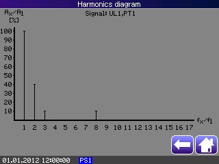
• Harmonic waves of feeder currents and voltages
(up to 17 harmonic wave on display)
• Circuit-breaker wear monitoring
• Trip circuit supervision (74TC)
• Fuse failure monitoring
• Current transformer supervision
• Potential transformer supervision
• 10 individual internal buffers for oscillographic fault records
|
|
 |
COMMUNICATION INTERFACES
• 1 USB-A (at front plate; for parameter setting)
• 1 Mini USB (at rear; for parameter setting)
• 1 CANBUS 0 (factory protocol)
• 1 CANBUS 1 for engine
• 1 CANBUS 2 for engine
• RS422/RS485 port port (Modbus RTU)
• Fiber optic interfaces (Line diff. Protection / SCADA)
• RJ45 (rear)
PROTOCOLS
• CANBUS 0 (factory protocol)
• CANBUS 1/2 (engine control: CATERPILLAR, DEUTZ, MTU, VOLVO, ...)
• PROFIBUS DP
• MODBUS RTU
• Modbus TCP/IP
• IEC60870-5-103
• IEC61850
IEC61850 NETWORK TOPOLOGY
• STAR
• RING(RSTP)
• HSR
• PRP
PLC
Powerful PLC functionality. A large number of PLC logics and function blocks, user programmable inputs and outputs, large numbers of predefined logical results such as event numbers allows user powerful control and automation functions.
CONTROLS
• Programmable inputs and outputs
• Programmable interlocking at station level
• Control and Interlocking of up to 2 switching devices
• Programmable functions for Power Management System (PMS)
|
|
 |
HMI
Display :
• Large full colour touch screen with user friendly interface
• Customisable Menu Screens
Keys :
• Keys on touch screen and front
• Switch Functions (optional)
LEDs:
• 8 programmable LEDs
• 3 status LEDs
• Graphical, programmable LEDs on touch screen
ANALOG INPUTS FOR MEASURING AND PROTECTION
• 3 × CTs for feeder phase current (1A,5A)
• 1 × CT for ground current or sensitive ground current (2-3000mA,1A,5A)
• 3 × PT for feeder voltage (0 ... 1100V AC)
• 3 × PT for BUS1 voltage
• 3 × PT for BUS2 voltage
• 1 × PT neutral voltage displacement input
Analog Inputs and Outputs
• 4 pcs Analog inputs (4-20mA)
• and 2 pcs Analog Outputs (4-20mA)
• and/or 2 pcs Analog Outputs (+/- 20mA or +/- 10V; changeover by extra terminals and wired bridge)
• and/or 1 pcs Analog Putput (PWM)
|
|
 |
BINARY I/O
User programmable binary inputs
• 5 binary inputs (standard)
• 19 binary inputs(optional)
User programmable binary/relay outputs
• 5 binary outputs(standard)
• 12 binary outputs(optional)
ALARMS
|
• 449 user programmable alarms
• 50 user programmable alarm groups
The alarm page on Compact dysplay is automatical active after alarm or trip. With detail user defined description for each Alarm or Trip and chronological order, the user has real ,simple and detail overview about what happened?
|
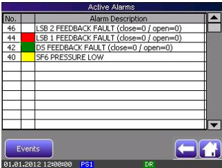 |
On trip or alarm the alarm page is automatical active and with detail user defined description for each Alarm/Trip and chronological appearance, the user has real and simple overview about what happened.
8 LEDs are user programmable. Also there is possibility to define graphical user defined alarm page with graphical color" LEDs".
ANNUNCIATOR PAGE:
• 16, 32 or 64 user programmable rows, with graphical color states and with user defined text description.
EVENT RECORDER
SYMAP®-Compact(+) automatically collects and saves all activated events The event history saves up to 10000 events by using the first-in-first-out (FIFO) principle. Each event provides information such as:
• the consecutive number,
• the event number,
• the event text, and
• date and time stamp.
FAULT RECORDER
SYMAP®-Compact(+) automatically collects and saves all activated events related referring to protection functions by the following attributes:
• all relevant file informationen (record number, trigger-event number, event text, date and time stamp) and
• all available measuring values of current, voltage and frequency (depending on the SYMAP®-Compact(+) device variant) for one record
A maximum of 1.000 protection function events can be saved. In case of overflow, the system will use the FIFO principle and automatically close out the oldest of the open trip events.
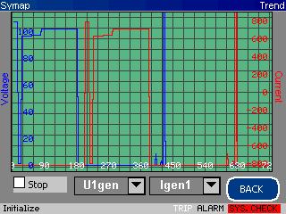
TRENDS* (Option)
• Current meters
• Voltage meters
• Ground values
• Frequency meters
• Power meters
• Harmonic waves
• Analog inputs
|
|
|
 |
| |
Optional:
• Saving data via SD memory card
• User defined trend elements*
• User defined trend elements with trigger for start and stop*
• Backup Parameter file*
DISTURBANCE RECORDER(option)
The device is equipped with internal 20 MB memory for buffering the measuring data. That internal memory can be devided in up to 10 idividual memory sections.
Each buffer provides the following states:
• “ready“
• “recording“
• “data“
• “backup“
• “inactive“
After the first buffer is filled and the next is in use the first one will be copied on the SD card.
Diagnostics and Monitoring
SYMAP® Compact has three microprocessors that supervise each other, providing a watchdog system. Important functions are laid out in a double redundancy combination, operating independently with the second processor. Connected separately, an optional unit for short circuit protection operates parallel to the SYMAP® Compact device and will do so even if the entire voltage fails.
SYMAP® Compact provides various diagnostic and monitoring functions as follows:
• All memories (ROMs, RAMs, EEPROMs)
• All analog reference voltages
• Automated test sequences
• Control power ON/OFF of SYMAP® Compact
• Binary input and output for control logic
The following supervising systems are offered by SYMAP® Compact :
• Self diagnostics of SYMAP® Compact
• The inputs of analog data (auxiliary circuit)
• The status and position of switching device and motor's ON-OFF status
• Supervising power supply of trip coil
• Gas pressure
• Temperature inside panel
• Each operating life of breaker (hours)
HARDWARE
Housing:
• small special design from stainless steel and aluminium (suitable for aggressive environment)
Terminals:
• pluggable terminal blocks
Display :
• large full colour touch screen
LEDs:
• 8 programmable LEDs plus 3 status LEDs
EXTENDED BOARDS (special applications)
• extra binary inputs and outputs: yes
• PT100, 4-20mA, 0-10 V: yes
SOFTWARE AND ACCESSORY
• "SYMAP Compact Parameter Tool" SCPT ( NEW software )
• Graphic design tool
• etc
• USB cabel for programming
|