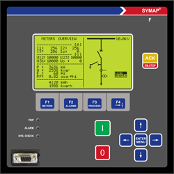
SYMAP® - Advanced Feeder Protection relay
SYMAP® F is designed for land and marine applications for protection, control, measurement and monitoring of low and medium voltages power systems.
All protection functions in SYMAP® F can be activated simultaneously, and there are no limits to using all of them at the same time.
Hence follows, that SYMAP ® F can be used in different switchgear and network applications.
SWICHGEAR Control and Interlocking
• single busbar
• double busbar
• duplex systems;
• interlocking at feeder level;
• interlocking at station level
|
|
|
NETWORKS
• isolated networks,
• resonant-earthed networks and
• solidly, and partially earthed networks
|
|
 |
PROTECTION APPLICATIONS
| 24 |
Overexcitation protection |
|
|
| 25/A |
Synchrocheck |
|
|
| 27 |
Undervoltage, instantaneous, definite time |
|
|
| 27 B |
BUS undervoltage, definite time |
|
|
| 32 |
Overload relay |
|
|
| 46 |
Reverse phase current |
|
|
| 47 |
Phase sequence voltage |
|
|
| 49 |
Thermal overload protection |
|
|
| 50 BF |
Breaker failure |
|
|
| 50 |
Overcurrent, instantaneous |
|
|
| 50 G/N |
Current earth fault, instantaneous |
|
|
| 51 |
AC time overcurrent, definite time, IDMT |
|
|
| 51 G/N |
AC ground overcurrent, definite time, IDMT |
|
|
| 59 |
Overvoltage relay, instantaneous, definite time, normal inverse |
|
|
| 59 B |
BUS overvoltage relay, definite time |
|
|
| 59 N |
Residual overvoltage |
|
|
| 64 |
Ground overvoltage |
|
|
| 67 AC |
AC directional overcurrent, definite time, IDMT |
|
|
| 67GS/GD |
directional earth fault, definite time |
|
|
| 78 |
Vector surge supervision |
|
|
| 79 |
Auto reclosing |
|
|
| 81 |
Frequency supervision |
|
|
| 81 B |
BUS frequency supervision |
|
|
| 86 |
Electrical lock out |
|
|
| 94 |
Trip circuit supervision |
|
|
| 95 i |
Inrush blocking |
|
|
| -- FF |
Fuse failure (voltages) |
|
|
| -- FL |
Fault locator
|
|
|
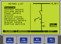
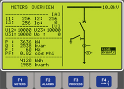
MONITORING AND MEASUREMENT FUNCTIONS
• 3 × phase-to-phase and line voltages of feeder and BUS1
• 3 × phase feeder current (average/max. value)
• Frequencies of all systems (min./max. value)
• Ground current and voltage (max. value)
• Active and reactive power of each phase
• Active and reactive ground power
• Power factor of each phase
• Active and reactive power counter (reverse and forward, constant and temporary)
• Operating hours
• Breaker cycles (life time)
• Harmonic waves of feeder current and voltage (up to 5th harmonic wave)
• Circuit-breaker wear monitoring
• Trip circuit supervision (94)
• Fuse failure monitor
• 5 oscillographic fault records
|
|
|
COMMUNICATION INTERFACES
• 1 RS232 programming on front or rear
• 1 CANBUS interlocking, CB control, power management system..,
• RS422/RS485 port
• Fiber optic
• RJ45
PROTOCOLS
• PROFIBUS DP
• MODBUS
• IEC60870-5-103
• IEC61850
PLC - powerful PLC function
Powerful PLC function.
A large number of PLC functions and blocks, user programmable inputs and outputs, large numbers of predefined logical results as event numbers allows user powerful control and automation functions.
CONTROLS
• programmable inputs and outputs
• programmable interlocking
• five CB control
• programmable PMS functions
Hardware:
Housing: : small, special design from steel and aluminium (suitable for aggressive environment)
Terminals: pluggable
Display : large graphical LCDisplay
ANALOG INPUTS FOR MEASURING AND PROTECTION
• 3 × CT for feeder current
• 1 × CT for ground current or sensitive ground current
• 3 × PT for feeder voltage
• 3 × PT for BUS1 voltage
• 1 × PT for ground voltage
Option:
• 3 × PT for BUS2 voltage
Analog I/O 0-20mA
• 2 x Analog outputs 4-20 mA (optional and hardware depending)
• 2 x Analog outputs 4-20 mA (optional and hardware depending)
Binary I/O
Configurable binary inputs
• 14(20) binary inputs(basic unit)
Configurable binary outputs (output relays)
• 8 binary outputs
• 1 lock out relay
• 1 synchro on relay
• 2 shunts
• 4 binary outputs optional in basic card
Other functions:
ALARMS
• 80 configurable alarms
• 20 configurable groups
Two rows text description for each Alarm/Trip in chronological order.
Annunciator Page:
• 16 or 32 graphical states with user defined text description
Event History
SYMAP® automatically collects and stores all activated events indicating their number, title, coming/going status, and time stamp. A maximum of 5.000 events can be stored. In case of overflow, data overwriting operates according to the first-in-first-out (FIFO) principle.
Detailed Protection Function History
SYMAP® F automatically collects and stores all activated events related to protection functions with a time stamp.
• Event number
• Event title
• Time stamp
• Pickup or trip value (with fault phase indication)
• Setting value
• Trip time
• 3-line voltage and current pickup, synchronized with the trip event
A maximum of 1.000 protection function events can be stored. In case of overflow, the oldest data will be recorded over.
Data Recorder (Option)
• Number of samples (6 - 72)
• Recording period (5 - 60 sec)
• Pre-trigger (0 - 100%)
• Trigger event (stop for recorder)
Diagnostics and Monitoring
SYMAP® F has three microprocessors that supervise each other, providing a watchdog system. Important functions are laid out in a double redundancy combination, operating independently with the second processor. Connected separately, an optional unit for short circuit protection operates parallel to the SYMAP® F device and will do so even if the entire voltage fails.
SYMAP® F provides various diagnostic and monitoring functions as follows:
• All memories (ROMs, RAMs, EEPROMs)
• All analog reference voltages
• Automated test sequences
• Control power ON/OFF of SYMAP® F
• Binary input and output for control logic
The following supervising systems are offered by SYMAP® F:
• Self diagnostics of SYMAP® F
• The inputs of analog data (auxiliary circuit)
• The status and position of switching device and motor's on-off status
• Supervising supply of trip coil
• Gas pressure
• Temperature inside panel
• Each operating life of breaker (hours)
Extended Boards (special applications)
• extra binary inputs and outputs: yes
• PT100: yes
Software and accessory:
• Parameter Tool
• Recorder Tool
• Modbus Tool
• History Tool
• “SYMAP Parameter Tool (SPT)” ( NEW software, license is required )
• Firmware Tool
• • Communication cable
Firmware and SPT software:
• Multilingual
|